Coffee Grinder

During my Junior year of college, I had to take many challenging engineering classes. Two of which was MECH 340, for Mechanical Engineering Design and MECH 308, for Finite Element Analysis (FEA). In the previous semester in the fall, I took CIVL 311, for Strengths of Materials, where you discussed deflections, stress and many other structural or strength fundamentals, and it was hard. During that time, I had some classmates (in other classes, not in 311) and students tell me that MECH 340 was CIVL 311 on steroids and it would be a lot more hard, thankfully, it was not. In 340, there was a lot of mechanical aspects which were discussed such as gears, more stresses, bearings and other components, and using the knowledge from that, had to complete a final project. This final project was to build a coffee grinder.

A couple ideas were thought of on how to build this grinder. The first was made from steel and had a structure/tower like design. It had an industrial feel but felt that it would be too heavy and hard to assemble. Its also steel and could rust, which for a food related item, is not good. The second was made to get a more clean look, and it featured a small opening to insert the coffee beans, This idea/design helped transition to the final design with small modifications being made long the way. However, during assembly, the hole was ditched since it would be hard to load the coffee and some may get stuck. A door which opened exposing everything was more convenient, and the professor liked the clean look and how it all closed up. The base of the grinder more or less stayed the same throughout the project.

The final design was a modified version of the second idea with a few changes. These changes were either done before the part was made or after it was made, in the sense of misreading values or building the part then adding it when it wasn’t on the original drawings. The final design which we came up with is seen below.

The general idea of the activity to start the grinder was to design a pair of shafts, (input and output) which were connected to each other with a pair of bevel gears. Our main task was to find which size shaft would be best fit for the job; with the given materials and how long the shaft would last based on the stresses and endurance life. Using MS excel, the moments, reactions, stresses and factor of safety were found, using this value, we can see if the device would or would not have infinite life, and if it didn’t, how many cycles it would have before it broke. In the preliminary analysis based on rough estimates on the forces which may be seen while the machine is in use, the diameter at each region can be found. For simplicity, we can find the largest bearing which is needed and use that at each location. Once that value was found, we would move up to the next nominal sized bearing, which in this case was 12mm. However, since the pinion’s face was just over 9mm, a 12mm shaft diameter at that part would not work, to account for this, a reduced section was added which allowed a larger bearing to be used but a smaller section which the pinon would be pressed on.

Once the lengths and diameter of the shafts were found, design of the grinder could be started. Using SolidWorks, I designed the grinder, starting with the shafts and the bearing blocks, then I thought of the design for the structure of the grinder. I wanted to enclose the device to contain all the grindings and make it look more clean/nicer looking. The first design had a more industrial look but it would be made from steel and bolted together, a small drawback to this would be it would be heavy and at the end, since this a food related product, a material which does not corrode or cause any health concerns would be chosen.

Adjuster

The main objective of the grinder was to grind coffee, however, many grinders are adjustable so you can fine tune it to get the best tasting coffee. This was an optional requirement for the activity, but if we are going to do it once, might as well do it right and challenge ourselves. After a lot of thinking, I thought of a way on how we can adjust the grind, unlike common coffee grinders where you adjust the burr on the shaft to make it more fine or coarse, we opted to adjust the outer part of the grinder with a giant nut. The part would be press-fitted into the adjuster where it can be raised or lowered to adjust the ground size. This made it easier to run calculations since the region where the force was applied was at the same point. A small recess was cut in the top of the adjuster to make the top of the grinder flush, and if the press fit wasn’t tight enough, it will hit the side of the recess and stop its rotation/allow it to work still.

The original idea was to cast both parts due to their size and finish it up on the lathe, but there were large enough pieces of scrap which worked. and one had a lot of material removed already so it made the process a lot faster.

For the adjuster nut, it was turned and bored on the lathe and was finished on CNC mill. Since the threads are very deep, (2 1/2 – 4 UNC) compared to most threads, the shop did not have the proper tooling to make that deep of a cut, so the part had to be done on the CNC where a rotary V cutter was used. The instructor helped make the G-code for it.

Shaft and Bearings

During the manufacturing of this component, we received the stock for the shafts, however, there was a slight problem, it was too small. The shaft’s OD was 12mm, and the original plans which we had required at least 14mm, so we had to move down to the next nominal size, which was 10mm, this made the shaft not reach infinite life, but it was still enough to operate properly and not break, and get a lot of use before it did. This also made it a tiny bit easier for the burr since the bore for it was already at 10mm. Unfortiently, this simplicity caused a small problem, since the bore for the bearings and the burr would in theory be at the same size, we would need to be able to slide the bearing onto the shaft to its shoulder while still having enough space for a press fit for the burr, this distance would be around 4in and it may be hard with the tools which we have in the shop. After the shaft was turned, during a test fit with the bearings which we got, (6900-2Z), we found that the ID of the bearing was smaller than the ID for the burr, due to this, this eliminated the possibility of the burr press fit. With assistance from one of the shop technicians, we decided to turn the shaft to where the bearing would slide on and braze the burr on to the shaft. However before we could do that, a few other pieces had to be on the shaft since the OD of the burr would be larger and they would not be able to be installed afterwards. Unfortiently, the plans were misread and the shaft was made too long so we had to grind the braze and remove the burr, luckily, nothing broke

Bearing
Bearing Block
Base Cover
Grinder Burr (Outer)
Adjuster
Burr
Output shaft Stack-up

Power Transfer

Another design decision which we made were how the gear and pinion were going to be attached. For the input shaft, we opted to the original idea to press fit it, this allowed us to get a good feel for the gear mesh and adjust it by pressing it further onto the shaft. For the output shaft, we decided to use a set screw, this would make it easier to assemble the project since that part can be added and locked in place once everything was set up. Since the bearing block B looked too close to the gear, a small slot was made to give it extra clearance.

Once this was done, the shafts were more or less done. But we still needed a handle to power the device. Using aluminum, I milled a handle and drilled a hole which slid onto the input shaft where a screw can be used to tighten it onto the shaft and hold it in place. In total, there were two lever arms which were machined. The first one was made by eye but the slot/counterbore where the screw set was too wide and too deep. Having it too wide didn’t affect it a whole lot besides it’s appearance but since it was too deep, it cut though the side of the hole which mounted onto the shaft and when the screw was tightened to where it was able to turn and grind, we noticed that the part had permanently deformed and failed. Since aluminum isn’t as elastic as steel and it tends to be buckle in some cases, this is why it failed. To improve and fix this, a new handle was made at the same size but the slot for the screw was large enough for the screw head and the counterbore was not as deep. At the same time, we decided to stay with the machined finish instead of buffing it and not add any decorative slots. I personally like the look from the cutter on the part and it matches the other parts which were made.

Originally this part was going to be casted out of aluminum then cleaned up on the mill but we decided to mill the part since it was a lot faster, 1hr vs 2-3hrs and if something happened, which it did, it would be easier to redo the part. There were also stress and deflection worries for it and that it would fail.

We also had the opportunity to use a bronze handle for the project, but since the part was extremely heavy, we didn’t want to add any extra stresses or strain to the device from its weight, so we decided to turn one instead. We wanted to use it for the bling factor but our eyes were bigger than our brains, luckily this was an easy part to replace or change out. To allow the handle to rotate during use, a long bolt was used to attach the handle to the lever, which is threaded for the bolt. However, if the handle bolt isn’t tight, it may unscrew itself during use.

Structure

For the project, the design of what the grinder would look like is up to the team, to design on SolidWorks and build. Since I was very enthusiastic to start the project and wanted to keep the product, I was the one who designed the project. I was also the one who had the most experience with the CAD software. I started designing this during activity 4 for the class. Knowing that the metal shop had a large supply of hardwood countertops, I decided to use that as the choice of material for the grinder. These materials were walnut and maple, I picked them since they were hardwoods, had a nice contrast with one another, and once finish was added, would make the project pop, which it did. In addition, the finger joint pattern on it was cool and it can also symbolize dark and light roast coffee.

The base consisted of walnut, and the maple was for the top part. The wood was originally 1 1/2″ and 2″ thick, so the pieces were resawed on the table saw. Using the bandsaw in this case would’ve been better, but the blade on it was dull and the table saw was the next option, but it made a clean cut so at the end, it worked. The parts were all cut on the miter saw and table saw, all holes were drilled on the drill press with a forester bit, luckily the bearings which were purchased were a hair smaller than one of the bits so it made a good fit. In addition to using the saws to cut the pieces, a drum sander was used to bring the parts into thickness, however the scale was off so the parts are 1/32″ thicker than they should be.

For this part, a CNC router was used to cut a few of the holes, these locations were: the front and rear panel for the opening for the drawer (for grain match) and where the adjuster sticks out, and the holes for the cover of the base and the hole for the adjuster nut. The CNC was used for those two holes since there wasn’t a drill bit large enough. Next to that, a laser engraver was used to do the decals, warnings and other labels, and luckily, the person who was running the engraver noticed a mistake in our spelling; course and coarse are not the same.

All the parts were drilled, countersunk and screwed together, with around 50 screws. However with the stack up from the output shaft, we had to use dowels to hold the grinder to the base, and is held on with a tiny amount of glue, however for travel/carry, its best to hold it by base, not the top.

Finishing Touches

After all the parts were done, there were some finishing touches which had to be done. One idea which I had was to make a scoop, something small which can be used to insert the coffee beans without the user overfilling. So by eye, I made one, with a ball and flat end endmill, I also buffed it to a shine. In addition to the scoop, a mount was made to attach it to the base, this was made similarly to its mating part on the mill. The scoop is very thick and is overkill.

To protect the grinder, wipe on poly was applied to it, it also helped bring out the color in the wood, about 1.5 coats were applied.

In addition to the bearings being purchased, a drawer knob was also purchased, the original idea was to turn one on the lathe, but we opted to buy one instead. A second knob was purchased with the order too incase we had enough space for the adjuster pin to lock the adjuster while in use, but there was not enough space so a small knob was turned on the lathe and slid onto the bolt. A small funnel was 3D printed to help direct the beans into the grinder. This had a small cut in it to be able to be added onto the shaft after everything was together, however that made to more complicated and it was not easy; it looked better on paper.

Decisions and Revisions

Since the start of the project, there were a handful of design changes which were made, either intentional or unintentional. Many of the revisions can be seen earlier in the post.

The top part of the grinder was changed from a tower like design to the one which was built. A few changes to how the front panel was mounted and what it had one it was also changed. The Decal was enlarged, the hole was deleted and it was hinged on the grinder, not screwed directly on. A safety/how to part was also added to the inside of the front panel. The locations of the screws were also changed, in the design, they were mainly added to see how close to the bearings they would be and not have it interfere.

The shaft diameter and bearings were also changed, the diameter was originally meant to be 12mm but was changed to 10mm, respectively , the bearings were changed for the new shaft diameter but a smaller size bearing was chosen by the professor compared what we originally wanted, this did not affect the operation of the machine. The addition of the set screw to the gear was also done to combine the two parts and the burr was brazed on instead of being press fit.

The adjuster was originally meant to be casted then turned but a suitable piece of scrap was found and to lock it, it was going to have straight knurls on it but was changed to slot where a pin could be inserted. The hole for the burr was also changed and made a bit wider while machining it, this made it easier and gave more space for the funnel. The nut was machined similar to its male counterpart, but it was made a tiny bit thinner and it had to be finished on the CNC, not on the manual lathe.

Similar to the adjuster, the lever was going to be casted but was not due to the amount of work needed to make it and other stress and deflection concerns. A more rectangular one was made on the mill but with the part being too thin in a few places, it caused it to buckle and be scrapped. Compared to the 2nd one the final one did not have decorative slots and the location where the screw was located was thicker and only accounted for 1 screw, not 2, which is why the 2nd one had a wide area and had most likely failed.

The handle at one point was planned to be a bronze part which was found in the shop, but due to its weight and the idea that it could bend the shaft, damage the bearings or strip some of the screws, we opted to turn it on a wood lathe instead. This also made it match the rest of the assembly. I wanted to cast the parts because a can and it may look cool but we chose to make the parts another way.

The drawer walls were made thicker and a drawer knob was purchased. Additionally, the front was finished on the CNC to get the grain match from the butcher block instead of individually cut on the saws. A small bin was added to catch the grounds and a small slot was cut on one of the sides after being glued together to allow the screw for the knob to be countersunk and not stick out allowing the bin to fit.

Finite Element Analysis

As mentioned at the start of the post, one of the classes I took was FEA, and for that class there was a final project which you had to use FEA on and run a simulation on SolidWorks to test and compare your data and for that project, I decided to use the coffee grinder.

To simply the simulation, I created a second assembly with only bare essential parts and had the majority of it hidden. The simulation was used to compare the deflection in the shaft during use and the stresses at the fillets. To see if the locations of max stress which was specified earlier can be seen and determined and if the machine would fail in a jam case scenario.

There were two results which were gathered when the simulation was run, one for von misses stresses and another for deflection, on the x and y axis. The deflection on the output shaft from the x direction was similar to the hand calculations if we simplified the shafts to cantilevered beams with an overhanging load on each end. By doing this, we can use Beam equations to determine the deflections. However the deflection in the input shaft in the y direction had some error and wasn’t as accurate as the output shaft, this was most likely from how the simulation was run since the simulation was run backwards and the fixed end to make it jam was on the input shaft, not the output. I wanted to replicate where the forces were coming from similar to the original lab assignment.

For the von misses stresses, they were more close to their hand calculation counterpart. When the simulation was done, the max stress location was on the gears, so in theory, the gears would most likely fail before the shafts do, but that will be determined if it happens. In the preliminary calculations for the assignment, the locations of the stresses were calculated from the location of the moment in that region, knowing this, probes can be placed in those regions to find the stresses. Due to this being a rotating shaft, there will be a median and absolute moment which correlates in a minimum and maximin stress which are 180 degrees from one another. But the stress viewed from the probes may be a bit off since finding the location of maximum stress took a lot of trial and error to see which spot had the highest region.

Comparing the data calculated to what was simulated, some of the results were close and others were not. How I set up the simulation, I made the input shaft end fixed and added the forces to the output shaft just like the coffee grinder activity. Excel was used to make all the matrices and find the deflect while the data from the stresses were reused with the appropriate shaft diameters. Percent error was not calculated from these indifferences but the results were close enough.

Final Remarks

All in all, this was a fun project, I got to use a lot of large machines to make a small one. I enjoyed working with my team, everyone did their part and we were able to complete it. I made around 80% of the parts and designed the grinder, the other members help make the shafts and 3D prints the parts which needed to be printed, and they also helped make the final lab submission. This was my first physical group project in probably years due to Covid-19 and it was nice being back. At the same time to the lab submission, I made a user manual and a brochure and the packet which we submitted was over 80 pages long, this also included the drawings for each part. My classmates and professor were all amazed by the design and everyone’s design was unique and different, at the same time how everyone made the projects were cool, some 3D printed the whole project, others made it on the CNC mill and some used a waterjet. It was funny how after everyone was stressed to take the final (and died from it), we were all in the back of the class showing off our grinders and making some coffee.

Casting Robot Buddies

Ever since I started 3D Printing in High School, I have accumulated an army of Robot Buddies. The tiny robots are the MakerFair robots from Thingy verse. I like to print them since they are simple, require little infill, no support and they are fun to do. For example, I used this model to create my chess pieces for my chess set which I made in Highschool. However for that project, I used TinkerCAD to modify the robots.
At my university, we have a foundry in the metal shop which is used to cast parts for class projects, and like many things in the shop which required your hands to get dirty, I took interest in this and I wanted to cast something with it. The first thing which came to mind to make was a robot, however it required some modifications to be done from the original model. The robot would have to be fully redesigned and made from scratch, since there are a handful of things which would need to be done and it would be easier and take less time to have a start fresh.

I had some design aspects and things which I wanted to change or add to the robot. Of these, I wanted to change the “M” on the front of the robot to the school’s logo and include my name on the back. Since I am sand casting this, I would need to slice it in half where it can be parted in the mold and it would would be held together with some alignment pins on a board. At the same time, a 3-7deg draft angle would need to be added so when it came time to remove positive from the mold, it can be easily removed without any contact with the surface. An angled face is easier to remove than a squared side. Unfortiently, it was a lot easier said than done.

There were two patterns made, one which had a 3 degree draft, and the other which had either a 5 or 7 degree draft. These patterns were designed on SolidWorks, and ere3D printed on an a Creality 10 printer, luckily, the arts department on campus has a printer which I can use and I am more or less the only person who uses it.

First Pattern 3D Printed (With Raft)

These were mounted to a board which were used in the molding process. The process which put the sand over the pattern and compressed it took around two hours and required required a lot of pounding, Unfortiently, when the pattern was removed, some stuff came up with it. For the first casting, a small part between the legs got moved, and a part of the eyehole was removed as well. At the same time, some sand got stuck between the letters in the name. I expected this to happen since the spaces between the letters or inside it were small. When the part was poured, we realized a riser would be needed since when the part cooled down and shrunk (which happens during casting), there as a region of shrinkage on the back side, which faced up, there was also flashing in a few spots. Once the part was done, some filing and cutting was done to remove the bulk of the unwanted material.

Since there were some problems in these areas, a remake of the pattern was made to account for a larger draft angle, which is why two patterns were made. With time constraints with finals and a bit of rushing, it came out better but still had its problems. Since the second casting was done during finals week, I was a bit more rushed and stressed to do it. With the new pattern and the same board, I repeated the filling process. During the removal phase, a chunk of sand came out between the legs, however this was my fault since I forgot to put powder on that side of the part, which made the sand stick to the plastic, not slide out. Besides that mess up, it came out clean. But we forgot to add a riser, so when we poured, the shrinkage was on the front side (pattern was front side up unlike the first one) and the metal had to be removed between the legs on the bandsaw. In addition to this, there was a lot more flashing, this didn’t really affect the casting, but it took more work to remove and clean it up.

Overall, the manufacturing process for this robot took around 2-3 hours to do, from packing to pouring. For clean up and filing, that part took around an hour. However to 3D print the pattern, that part of the project took an additional 4-5 hours, but unlike the first pattern I did not use a raft on this one, initially I thought it would be a good idea, it was not and it took over an hour to remove, which is why I didn’t use it on the second pattern. Note, this is not including designing the robot on SolidWorks.

Robots waiting for Him to be casted and brought to life

All in all, the project was fun, are the castings perfect, no, but the imperfections on them make them unique and cool; at the same time, I had fun and learned a lot. I was able to design something on the CAD software and do some casting, and in some cases, it could be a once in a lifetime opportunity (I will probably cast this again to get a more clean casting in the following school year). This was my first time casting, when I was meant to do my first casting 2 years ago during one of my classes, Covid-19 had hit and I was unable to do it. I am happy that my lab instructor allowed me to do this. And yes, I had to print a mini version.

Mill Hammer

On the list of hammers, this one has a use and was a pain but a fun experience to make. This hammer has a few utilities and can have a few modifications done to it. This a mill hammer, one which can be used on a milling machine.

Mill Hammer

Like my other projects, I designed this on Solidworks, the process for this was similar to the Machinist Hammer, such that it would screw together and that there would be aluminum ends on it, but I wanted this tool to have a specific use for the mill, not just to hit stuff but to be used to adjust or tighten any of the bolts on the machine. (Since all the bolts on the machine are usually the same size.

CAD Model

On the CAD software, I made this, where there would be shaft with a head on it with some aluminum ends and a handle with a hex on the end. The original idea was to make the handle out of two halves but a single piece design was used instead. The 90deg attachment on it is used to get the contact of the hammer closer to the shaft, incase you want a more vertical contact or are in a tight space, it can be used instead. Also, the hammer head is long so this helps resolve that.

All the parts were mostly done on the lathe, with a few done on the mill, for that, the holes and the recessed section for my name was done on that machine. However, a hex needed to be cut, this posed a problem since the shop does not have any broaches for that size. Instead, a hole was drilled to the nominal size of the hex and the remaining was finished in a file and a good portion was done by using a bolt as a broach and powering though it with a hammer. But if I was to do this again, I would heat it up with the touch so it would be easier and it would help form it, not cut it. For the handle, that was one on the wood lathe like other projects.

All in all, the project was fun but it took a while, I would’ve spent more time on the threads to make them more perpendicular and thought of different methods to make the hex. But the ends can be removed, replaced or changed to rubber ends.

The Carver’s Mallet

This was one the projects that I’ve wanted to make for a while, its a simple one but in order to make it, I would need to use a lathe; luckily, when I was in college, the Art’s department had one to where I could build this project. The tool which I wanted to make was a carvers mallet.

The Mallet

For the basic design of it, it involves a big head and a handle, and some make it in two pieces where they can assemble it when they are done. For mines however, I made it as one part. The shop had some scrap wood from a table and I was able to cut them into spices and glue it together to make one large block which I was able to clean up, trim and turn on the lathe.

Block o’ Wood

I used a table saw to cut the corners off the block so it would be easier to turn and I used the bandsaw to cut parts off the side of the handle so it too would be easier to turn. Once everything was ready to go, I took around an hour to turn. The wood from the table was I think maple, I wanted to use a hardwood since its a hammer and would be hitting a lot of things. I applied 2 coats of finish and after a lot of work, it was done.

Come-Along

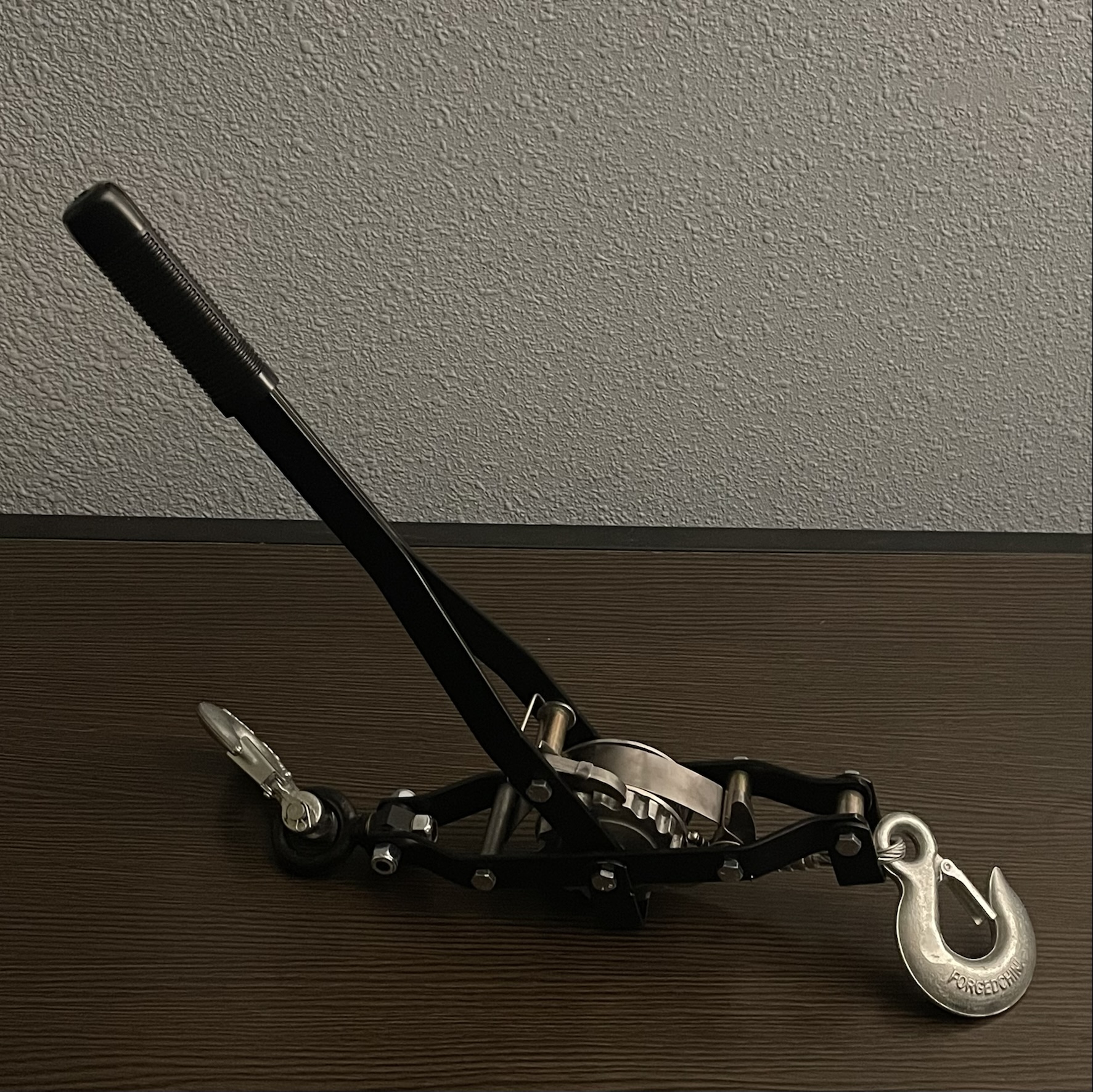
During my freshman year of college, my flowchart told me to take my manufacturing class. There, I was taught the basics of it such as casting, forming/bending, milling, turning, etc. Using these new skills which we were taught (and a set of plans), we were to use them to construct our final project, a Come-along.

The assembly

However, it wasn’t that straight forward; for starters, it had a lot of free time, which was good, during that time, I constructed my Machinist Hammer, the Nightstand, the Ultimate Laptop Desk and a few other things, which was good and there was nothing bad about it. But, things did turn bad. In the middle of the semester, COVID-19 had it and everything transitioned to online, this is a manufacturing, hands on, lab based class, which was not at all designed to be done online; unless if you have all the machinery and one of a kind parts for it. But before it had it, I was able to complete a handful of the parts, all except 2-6 of them. (one of which I had to remake since I lost it, and 3 required to be done on the CNC).

But in all said and done, once everything went back in person…17 months later, I was able to continue the construction of it and I was probably the only student in my class to complete it. While I was making it, it was like any other project, you make mistakes and either fix it or remake it, just how it is. For the general making of the parts, it took maybe 5-8 classes (3 hours a class). To make the parts, it consisted of cleaning up the parts/deburring, drilling and tapping a few holes, cutting and bending the parts, either by hand or with a press, and turning a few parts on a lathe as well as facing it on the mill. The winch was made from steel and the drum was cast aluminum. Also a few parts were provided due to it taking too much time to manufacture or it was an off the shelf part. Before final assembly, I was able to get it powder coated in a sleek black. I had also initially stamped my name into it but once the paint was added, it made it hard to read it.

Quick dry assembly before paint

For final assembly, it was better said than done and it involved a lot of banging. Like anything, your parts are not perfect and it requires tweaking, especially after the paint, you had to remove some of it to make sure they had properly fitted together, which involved assembling part of it, taking it apart, then repeating that one step 6+ times. At the same time, my drum guard piece was a bit of a tight fit to where it took an excessive beating with a hammer to fit in place and the spring in the one pawl required to be adjusted a few times to get enough force to lock it into place. After around 4-5 hours, it was finally done and assembled, but it did take an additional 30 mins to cut the bolts and clean it up.

Lastly, to show how much of an engineer you are, you are to test it by lifting a 500lb block of concrete and luckily, it was able to conquer it without any sweat, however the rubber handle grip thing did slide off… almost twice.

All in all, the project was a dream and a nightmare, it was fun making but it did teach me the importance on how things intertwine and link together how one small mess up could have a large impact later on, and close enough might not be close enough. Building it was fun and the assembly took a lot longer than I anticipated and it was filled with anger and rage. But I would do it again.

“Torpedo” Tapping Hammer

Next on my list of Hammers is a tiny one, something small and interesting but fun and easy to make. So I decided to build a small tapping hammer. (and yes I have a list on types of hammers which I want to make)

I got this idea from a freebee item at a career fair, a company had handed out little stress hammers and I thought they were funny and comical. At the same time, in my machining class, there was a small hammer for light-duty work to make starter punches. Using these things, it gave me an idea on something to build.

The original design was to use a piece of either 3/4″ or 7/8″ bar stick and mill it into shape however I was unable to find a piece of scrap of that size. I could have gotten a bigger piece and mill it into shape but I was using the lathe that day and my last hammer, the Ban Hammer, was made on the mill. I call it a tiny torpedo due to the shape of the hammer head being similar to a torpedo; one side has a ball end while the other has a small taper and it is roughly 3.75″ long and 3/4″ in diameter. For the handle I used cherry, and it was a cut off from the Katana and Wakizashi project. I had saved it from that project and this was the time to use it. I was able to turn it on the lathe to a nice shape and size which looked good and similarly to the ban hammer, I used a walnut wedge to hold it on. The hammer is small and comical, but for light duty work, it’ll get the job done.

Tapping Hammer compared to the Sledge hammer

Nightstand

During my freshman year of college, I lived in the dorms which was nice. However, I wanted to make a nightstand or small table to put next to my bed due to the beds being at their max height and you had to reach quite a far ways down to grab your phone or place things down. In the spring of 2020, during open lab and my manufacturing1 class, I made a nightstand.

To start off, I designed this on Solidworks, similarly to my other projects, there was more than one version to this. The first one included a small shelf instead of a drawer but I opted for a drawer for a closed and completed look.

For construction, I used 1 1/4″ angle iron, everything on the frame was mitered and welded together. For the side panels, I used 1/2″ oak plywood with a rabbet on them so they can be inserted and flush with the sides of the metal. They are bolted to the frame. The top is held on a similar way with it using carriage bolts to be flush with the top surface. I had to use plywood spacers in the inside to allow for clearance for the drawer slides. To build the drawer, I used rabbets to joint it together and the drawer bottom is inset to the sides. For the handle, I used some bar stock and welded one together, drilling and tapping it so I can attach it to the drawer face.

However during final assembly, I noticed a problem. When I had drilled the holes in the frame for the bolts, I measured all the holes in the same spot/distance from the edge, so when I assembled it, I had to use very thin nuts so I can clear the table top and the bolts holding that on. But luckily, I had enough space between the side panels and the side of the top to make it fit. I also had to chamfer the corners of the side panels so they can have clearance around the welds.

But once the project was assembled, it was sturdy and it can take a beating. The table weighs around 30lbs and I carried it to the dinning hall a few times due to the open lab ending late. For dimensions, it is around 16in wide/long and is around 28in high.

The Impossible Nut

Looks may be deceiving, yet the true mystery is always hidden. On my list of things which I wanted to make was an Impossible nut, if you do woodworking, this is the impossible nail’s cousin. I was watching an youtube video from This Only Tony and saw this idea and thought it would be a fun thing to tackle.

Construction of this is simple, just a steel shaft with some cuts and a relief for a 5/8 x 11 UNC threads (or any threads of your choice) and a…nut? But how does it get there and that is the question which this will answer, and before you ask, no I did not weld it or super glue it into place so I can take a photo.

With all jokes asside, this was an easy project, it took around 2-3 hrs to complete, I started by getting a piece of steel which I felt was thick enough then I cut a section off that. With the 2 parts, I faced and cleaned them up, on the longer end I cut a small section to accept a 1/4 x 20 UNC threads while on the other half, I bored and tapped the same threads (female, not male, internal hole). After counter boring the threads so I can screw it together all the way, I put it back onto the lathe, as 1 assembly and cut the relief for the threads.

Once it was to size, I used a die to cut the threads, then while the die was on it, I screwed the other half back on then cut the threads in the other direction. When that was done, the hard part was completed, for the nut I just used a piece of steel, cleaned it up, knurled the OD and drill and tap the hole. Then at the end, all I had to do was unscrew the rod, screw the nut on and reattach the other part and it was completed. the threads help hide the cut line to make it look seamless.

If you are looking for a fun project to do during the weekend, this can be it.

The Ban Hammer

During my time in college, I have a list of things which I would like to build, as one gets completed, another is thought of. One thing I wanted to make is a Sledge Hammer, which is what I made here.

The head of the hammer is a 1 3/4″ block of steel, machined to what it looks like. The edges are chamfered to give it an octagonal appearance. The hole for it is around 1″. While the head was made on a Lagun Milling machine, the other components were not (obviously). I made the other components in the woodshop on campus. The handle is made out of oak turned to size/what it looks like while the lower part was hand filed to make it easier to grip and fit my hand. The wedge that holds it on is made from walnut, while the metal one, which truely holds everything together is made from steel. For that part, we used an oxy acetylene torch to head up a piece of steel then I used a hammer and an anvil to beat it into shape.

For specs and other characteristics, the head weighs around 4lbs. Like said before, the handle is oak finished with wipe on poly and the head has a wax finish to protect it. The head is not hardened, but regardless of the task at hand, light or medium duty, it’ll do its job.

Pictures of it

Youtube Video of me making the head.

The Ultimate Laptop Desk

During my freshman year of college, I spent a good amount of time doing work in bed, your classes end late and you’d rather relax in bed while doing work than sitting at your desk. Unfortiently, your laptop gets hot, half the time your legs are where the fan inlets are and it can get pretty toasty, especially with a gaming laptop, 1 fan for each leg. To solve this problem, I designed not 1, but 7 laptop desks to resolve my problem, and this is how I created it.

To start off, I was starting my second semester and I had access to the university’s machine shop for a class, so during break before the semester started, I made a few designs. So I did what any other person would do and went to the internet to search for designs, what they could look like and what I should incorporate with it. For my case, I wanted to have a space for a mouse and mousepad, I hate using the touchpad, I wanted it wide enough so if someone else uses it or I grow, I can use it still without any problems, lastly, I wanted to have fans on the bottom for cooling, it was not required but a useful addition.

Version 1

This design was an idea that I saw online, something that can hold the device. This also included having a sleek 1 pipe design, with an exception to the back brace, this would have a single pipe with all the bends in it. There would be a top on it for the laptop and a bent piece of sheet metal which can be inserted to house a mousepad. Also , there will be spots for cooling on the bottom.

ProsCons
Narrow and compactNot much room for adjustment
StylishFlex/not enough support for the mouspad
Do not have the tools or skills to do the bends

Version 2

Version 2

Version 2 was similar to version 1 however, it was wider. It eliminated the need of the detachable mousepad. By doing so, it avoided/removed the addition to having a compartment or place to store the piece, it makes it more sturdy and space for fans and other hidden parts.

Version 3

Version 3 is just like its prior model, however, the fronts of the tubing are bent back up to reconnect to the top for more support and for strength. I do know know how thick the pipe is or if it would be able to handle the weight of the stuff on top of it. This also gives it a unique look to finish it off.

Version 4

When I started construction on the desk, I was told to use the material on the shelf to build it, however this posed a problem. There wasn’t enough tubing to make the design that I wanted, but there were some pieces of square tubing. So I improvised and used that. Using the plans which I printed, I measured and cut out the parts which I needed to get a rough shape and style which was similar to the original design. This is what it would look like from the parts that I cut.

Version 5

Version 5 is a revision of 4, to clean it up and make it look more nice and not like a welding disaster. I refined the shape and made it to a similar size/shape to version 2.

Version 6

For this version, the only difference from the previous one was the addition of arm rests, something to rest your arms on as you use your pc, they can be slid into the frame for storage and it wont take up any other space.